OSINT Jet · Reading light in a photograph
Shadow analysis for OSINT: test a photo’s claimed time
A long shadow is not a clock. But if a photograph’s public location and possible date are already known, a clear shadow can help test whether a claimed time makes sense. The useful question is usually “Does this time fit the scene?” rather than “What exact minute was this taken?”
Start with two observations: the direction the shadow travels across the ground and, when it can be measured properly, its length relative to the object. Direction and length answer different questions. Keeping them separate can expose a bad match that would survive either check alone.
Do you have enough information to begin?
Choose a stationary object whose base and shadow tip are visible: a post, a simple column or a straight sign support in a public place. A tree’s moving branches or the edge of a complicated roof can make the source of a shadow unclear. Check that the dark shape is a cast shadow, not a stain, a reflection or a different object.
- Location: independently establish the public scene first. Our image geolocation method covers that task.
- Date: record the candidate date or bounded set of dates. Upload time is not automatically capture time.
- Orientation: establish true north relative to the ground. The top of the photograph is not necessarily north.
- Geometry: identify a vertical object and a reasonably horizontal receiving surface. A slope or wall requires a different model.
If you cannot resolve orientation, keep the image as an unmeasured clue. Rotating a photograph until its shadow fits the desired answer would remove the independence of the test.
Turn a ground direction into a sunlight direction
NOAA’s solar glossary defines azimuth as a direction measured clockwise from true north and elevation as an angle above the horizon. Under that convention, north is 0°, east 90°, south 180° and west 270°.
For a vertical post on level ground lit by the sun, the shadow runs away from the sun. If the ground shadow points northeast at 45°, the corresponding horizontal direction toward the sun is 225°, southwest. Add 180° and wrap around at 360°.
That is a ground bearing, not an angle drawn against the edge of the screen. In an oblique photograph, perspective changes the apparent angles. Use known ground geometry to reconstruct the direction, or keep a broad interval and explain how you obtained it. A rotated map view needs its orientation recorded too.
Length offers a second check, with stricter conditions
For the same simple geometry, let H be the object’s real vertical height and L its shadow’s real horizontal length. The solar elevation is approximately atan(H / L). This is ordinary right-triangle geometry; it assumes the visible shadow belongs to that object and reaches level ground.
Do not divide the post’s pixel height by the shadow’s pixel length in an ordinary perspective photograph. Those two directions generally have different image scales. Use defensible real measurements or a justified reconstruction. If height or scale is unknown, the length check is unavailable, even when the direction check remains useful.
A small worked example: same length, wrong direction
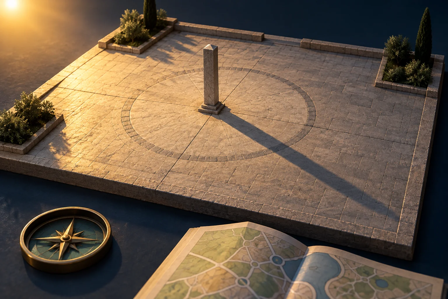
Invented geometry exercise: a 2-metre vertical post stands on a flat public-square model. Its measured ground shadow is 3 metres long and points at 45°. These are teaching inputs, not measurements from a real investigation.
The implied elevation is atan(2 / 3) ≈ 33.7°. If the shadow tip is uncertain and the length could be 2.8–3.2 metres, the elevation range is roughly 32.0–35.5°. That range is more useful than reporting a spurious tenth of a degree as certainty.
| Hypothetical solar position | Predicted ground shadow | Comparison with the exercise |
|---|---|---|
| A: azimuth 225°, elevation about 34° | Bearing 45°, length about 3 m | Both checks fit within the example’s precision. |
| B: azimuth 135°, elevation about 34° | Bearing 315°, length about 3 m | Length fits; direction does not. |
A and B are deliberately constructed comparison positions, not outputs claimed for a particular city or date. The lesson is that matching a shadow’s length alone can accept the wrong part of a solar path. Even a two-part match only supports compatibility; it does not identify the photographer or authenticate the file.
Run the time comparison without moving the goalposts
Write down the location, candidate date, claimed clock time and time zone before using a solar-position tool. Keep the original timezone notation and a separate normalized value. Our timestamp guide explains why a platform’s displayed time and a scene’s capture time should stay separate.
Use a documented calculator to obtain azimuth and elevation for the candidate inputs. Record the tool and input conventions. A concrete trap appears in the older NOAA calculator: west-positive longitude and timezone fields differ from many modern tools. Copying a signed coordinate without reading those labels can move the calculation to the wrong side of the world.
NOAA’s calculation notes also say its solar calculator is no longer actively maintained and describe atmospheric and precision limits. Use those notes as a reminder to document the model, not as a guarantee of minute-level accuracy. Near-horizon scenes, unclear tips and uneven ground need particular care.
Compare the predicted shadow bearing and usable length range with what you recorded. If you test several candidate times, list all of them. Do not quietly change the date, north direction or chosen object until one prediction fits.
End with a bounded conclusion
Use one of three outcomes: compatible with the tested inputs, inconsistent with the tested inputs, or not measurable from this image. For an inconsistency, check the orientation, time zone and geometry before suggesting a wrong caption. For compatibility, preserve alternative times or dates that also fit.
Public scene and location evidence:
Candidate date/time and time zone:
Object, ground surface and orientation method:
Observed shadow direction / usable length range:
Calculator, conventions and predicted values:
Agreement, conflict or missing measurement:
Conclusion and remaining alternatives:
A one-photo check can remain a short note. When several images, captions and dates conflict, the harder job is keeping each observation attached to the right version. OSINT Jet’s image investigation workflow can help organize those public clues into a reviewable case; it does not replace a defensible geometric measurement. Use the report template to document your comparison, and review current report options if you need the wider evidence organized.
Published 14 October 2026 · OSINT Jet